












English
028-8583 8313
English
2D Die Aperture Gauge(SC Series)
Wire Drawing Die Gauge
Product introduction
Key Features
Technical parameters
Downloads
FAQ
2D Die Aperture Gauge(SC Series)

2D Die Aperture Gauge(SC Series)

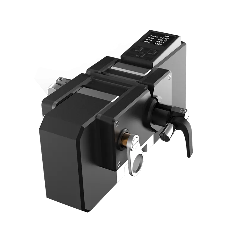
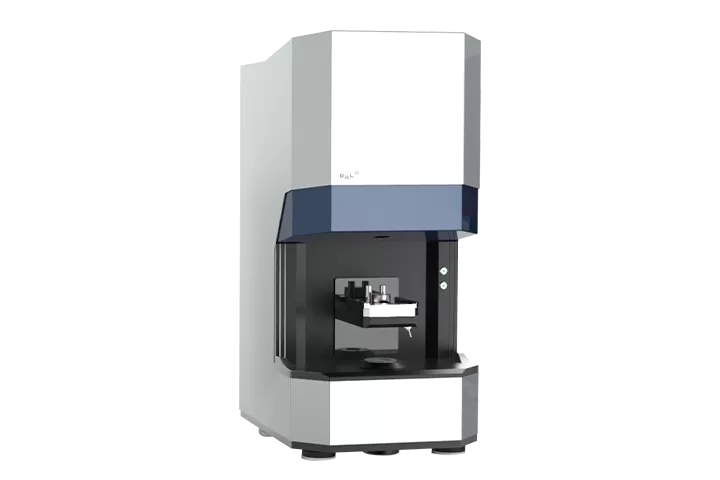
The 2D Die Aperture Gauge(SC Series) is a tailor-made automatic, high-speed, high-precision measuring instrument for wire drawing die and cable manufacturers. It supports fast auto-focusing and positioning on the reference plane for fully automatic measurement. Its integrated optical system with collimated light source, automatic lens switching and high-speed image collector realizes high-precision measurement across a wide aperture range.
Measurement Range
0.02~3.00mm
Measuring Range
Diameter, Ovality
Measuring Principle
Telecentric Optical Measurement Technology
Application Industries
Metal Wire Drawing, Wire & Cable

Product introduction

The 2D Die Aperture Gauge (SC Series) is developed specifically for wire drawing die manufacturers and cable producers. The gauge features auto-focusing, auto-positioning and automatic lens switching. Operators can complete measurements with one click. Equipped with collimated light source and high-speed imaging module, it covers a large aperture range, making die aperture inspection easier and more accurate.

-  Supports one-click measurement, auto-focusing and automatic lens switching
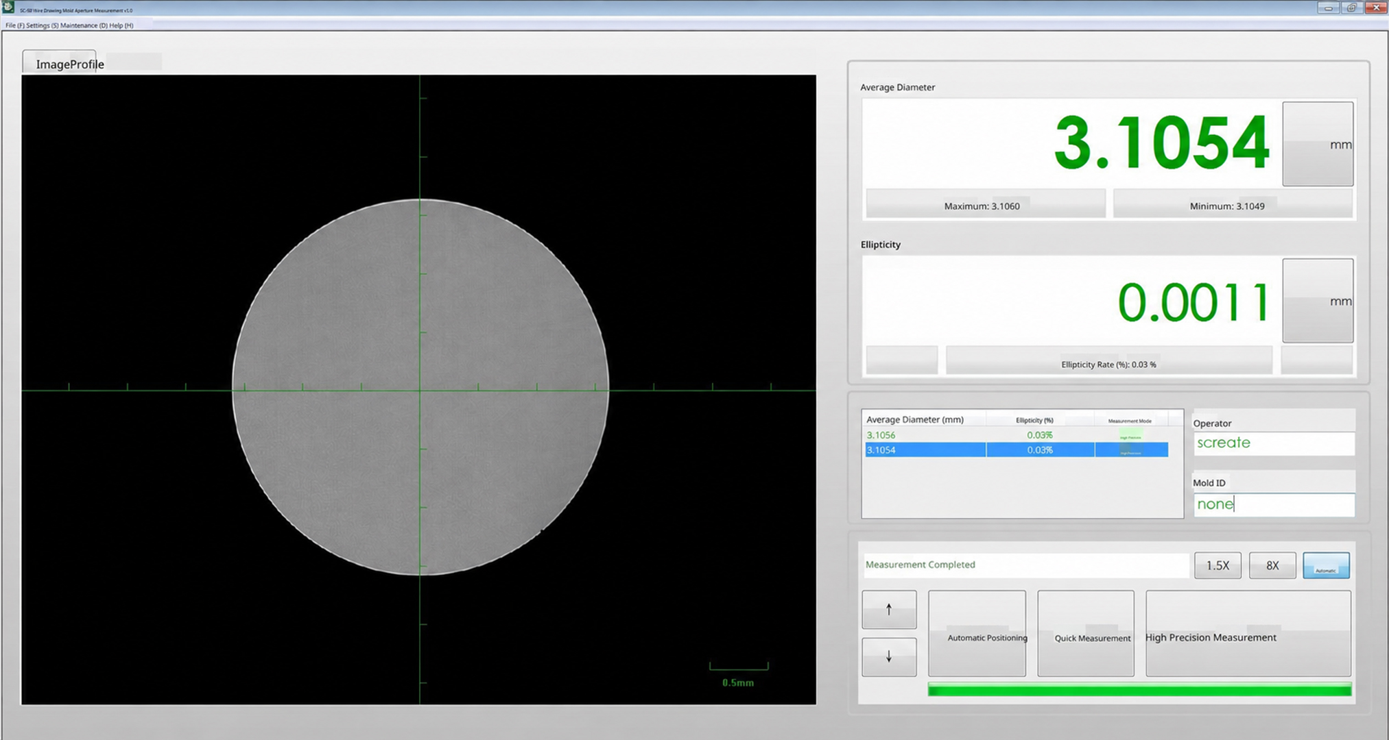
-  Supports visual measurement status display, showing measurement results such as aperture and ovality
-  Supports single-point / multi-point calibration; allows creation, import and export of measurement standards, and viewing calibration curves in advanced mode
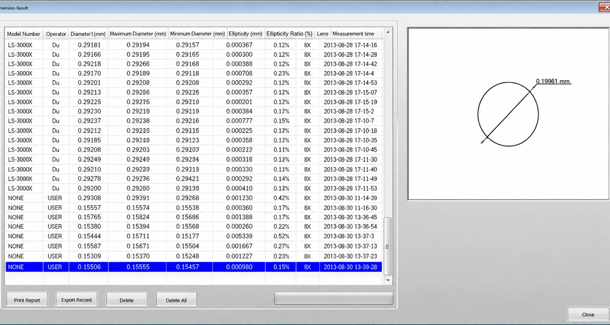
-  Supports automatic storage and export of measured data, storing up to 20,000 records, with Excel export and report printing available
-  Supports connection via a single USB cable for synchronous transmission of images and control signals; compatible with Windows 10/7
-  Supports self-service firmware upgrade

Key Features

One-click Measurement, User-friendly Interface

One-click Measurement, User-friendly Interface

Featuring auto-focusing system and automatic lens switching unit, it enables true one-click automatic measurement without manual operation. With a friendly and elegant HMI, users can quickly get started on the software even without professional knowledge.

Measurement Results Exportable

Measurement Results Exportable

Automatically saves every measurement result; supports export to Excel or TXT formats.

Technical parameters

Lens magnification 8X 1.5X
Inner diameter range (mm) 0.020–0.600 0.60–3.00
Repeatability (mm) ±0.0003 ±0.0012
Die outer diameter range (mm) 22.5–60
(concentricity between die inner and outer diameter better than 0.5 mm)
Die height range (mm) 5–25
Typical measuring time 3 s (fast mode), 7 s (high-precision mode)
Measurement report print Inner hole profile, diameter, ovality, etc.
Measurement data storage Automatic; exportable in MS Excel or TXT
Calibration & custom standards YES
Self-check YES
Software upgrade YES
Power supply 24VDC ±5%, Max. 36W
Data interface USB2.0
Operating environment Relative humidity 15–80%, temperature +15°C ~ +30°C
Storage environment Relative humidity 8–80%, temperature 0°C ~ +50°C
Instrument weight 17 kg

Downloads

Technical documents such as product manuals, datasheets and outline drawings

PDF
2D Die Aperture Gauge(SC Series)Brochure DownloadsPDF
⬇ Download

Frequently Asked Questions

Answers to frequently asked questions about 2D Die Aperture Gauge(SC Series)

Q How to Select the Lens Magnification for Different Die Bore Sizes?

Lens Magnification

2D Measurement Range (mm)

3D Measurement Range (mm)

20X

0.015-0.200

0.020-0.035

10X

0.035 - 0.450

0.035 - 0.110

3X

0.110 - 1.50

0.110 - 1.000

1X

0.350 - 5.00

0.400 - 4.000

0.5X

0.700 - 9.00

0.800 -8.500

0.25X

1.00-20.00

2.00-20.00

0.1X

4.00-45.00

4.00-45.00

Q What should I do if the die bore cannot be located?
  1. Switch to a lower-magnification lens. For example, if you are using a 10× lens, switch to .

  2. Move the die stage and look for a bright spot in the software image. Once found, move the bright spot to the center of the image, then adjust the Z-axis until the double-ring image becomes clear.

  3. Switch back to the original magnification. Move the die stage again to center the bright spot, then adjust the Z-axis until the double-ring image is clear. If the image is already clear after switching back, no further Z-axis adjustment is needed.

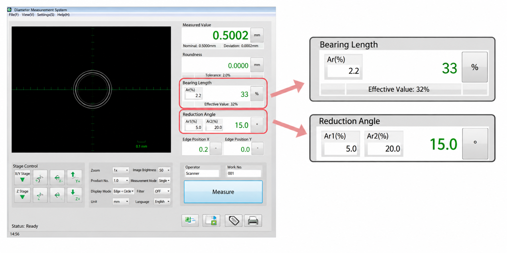
Q What do Ar(%), Ar1(%), and Ar2(%) mean in the measurement software?

Ar(%) is an input parameter used to calculate the bearing length.
Ar1(%) and Ar2(%) are input parameters used to calculate the reduction angle. Their positions in the measurement interface are shown below:

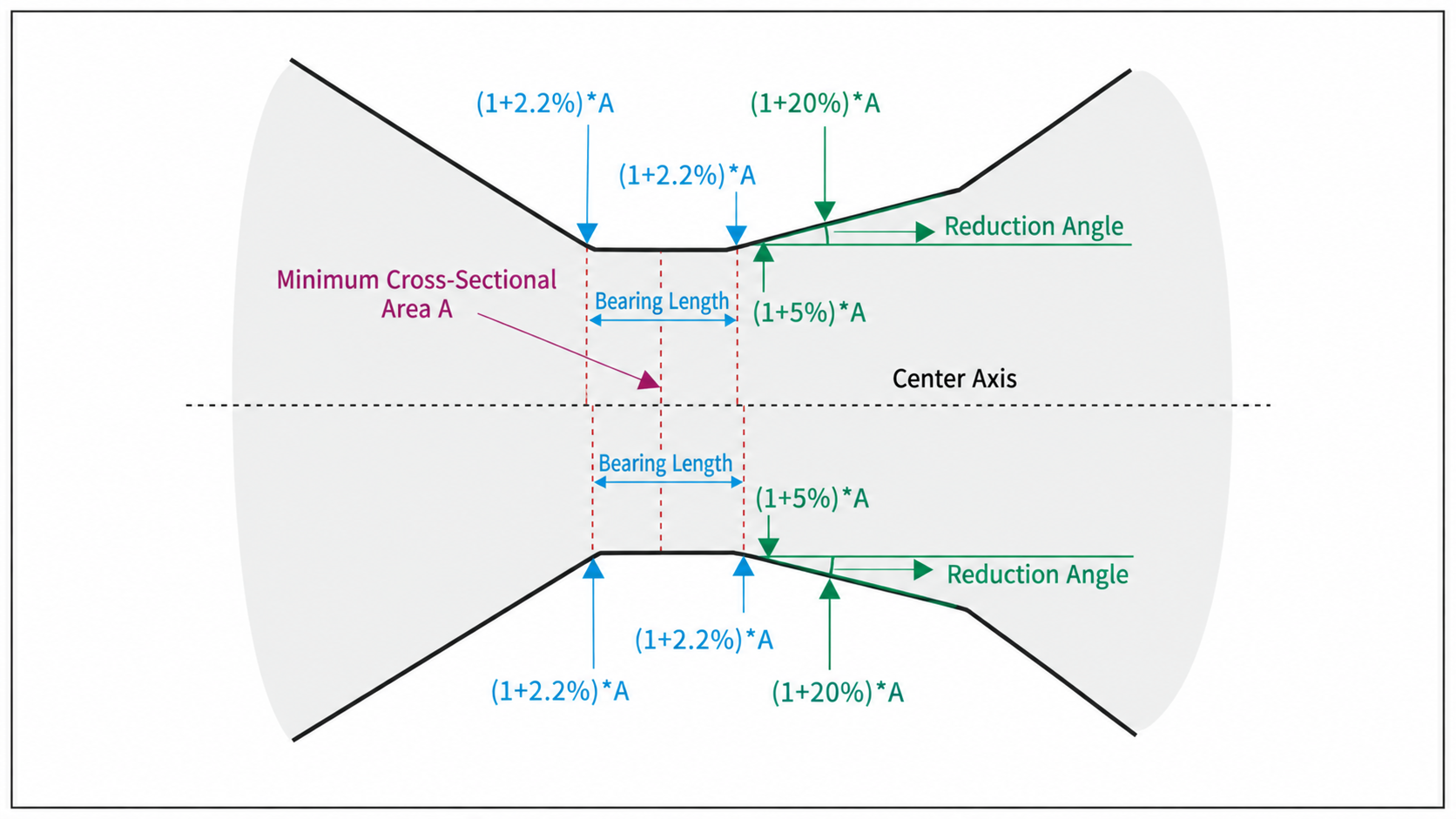
In the example above, Ar(%) = 2.2. This means the bearing length is calculated based on the position where the die bore cross-sectional area reaches (1 + 2.2%) × A, where A is the minimum cross-sectional area of the die bore.

Starting from the minimum area A (purple dashed line below), the area increases by 2.2%, creating two positions as indicated by the blue arrows. The calculated bearing length in this example is 33%.

Ar1(%) = 5.0 and Ar2(%) = 20.0. The reduction angle is calculated using the positions where the die bore cross-sectional area reaches (1 + 5.0%) × A and (1 + 20.0%) × A.

Starting from the minimum area A (purple dashed line below), the area increases by 5% and 20%, creating two positions shown by the green arrows. The calculated reduction angle in this example is 15°.

Note: The die bore cross-sectional area is calculated from the radius along the die center axis, so two bearing length values and two reduction angle values can be obtained.

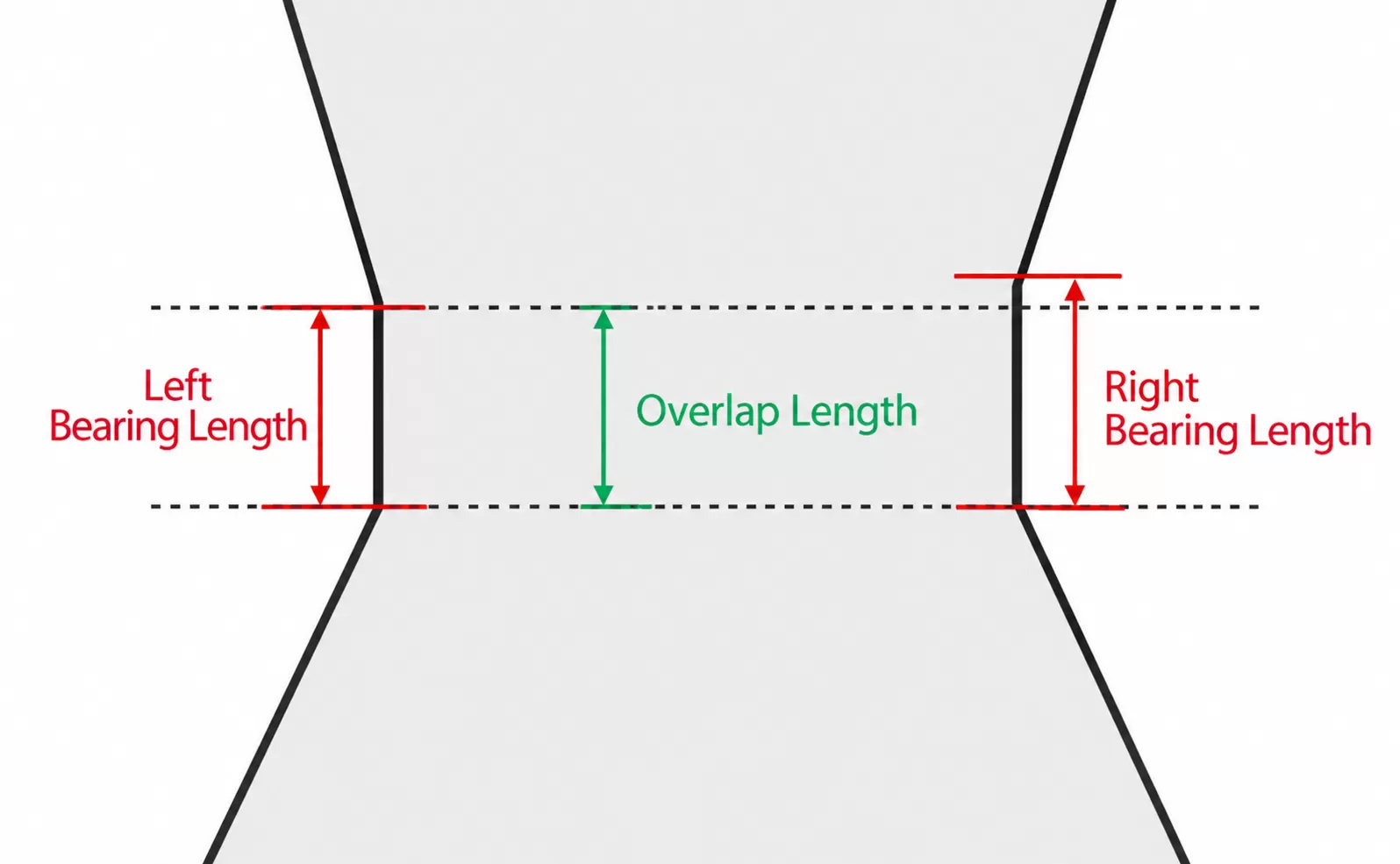
Q What does the effective bearing length mean?

The effective bearing length is calculated using the following formula:

Effective Bearing Length = (Overlap of the Left and Right Bearing Zones + (Left Bearing Length + Right Bearing Length) / 2) / 2

This value is designed to represent the actual effective bearing length of the wire drawing die as accurately as possible.

Fast Delivery & Comprehensive Support

Provides end-to-end support from product selection to production line operation through on-site guidance and after-sales technical support.