












English
028-8583 8313
English
3D Die Profile Gauge(DM Series)
Wire Drawing Die Gauge
Product Introduction
Key Features
Technical Parameters
Downloads
FAQ
3D Die Profile Gauge(DM Series)

3D Die Profile Gauge(DM Series)

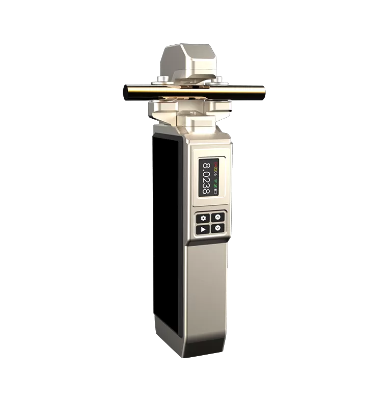
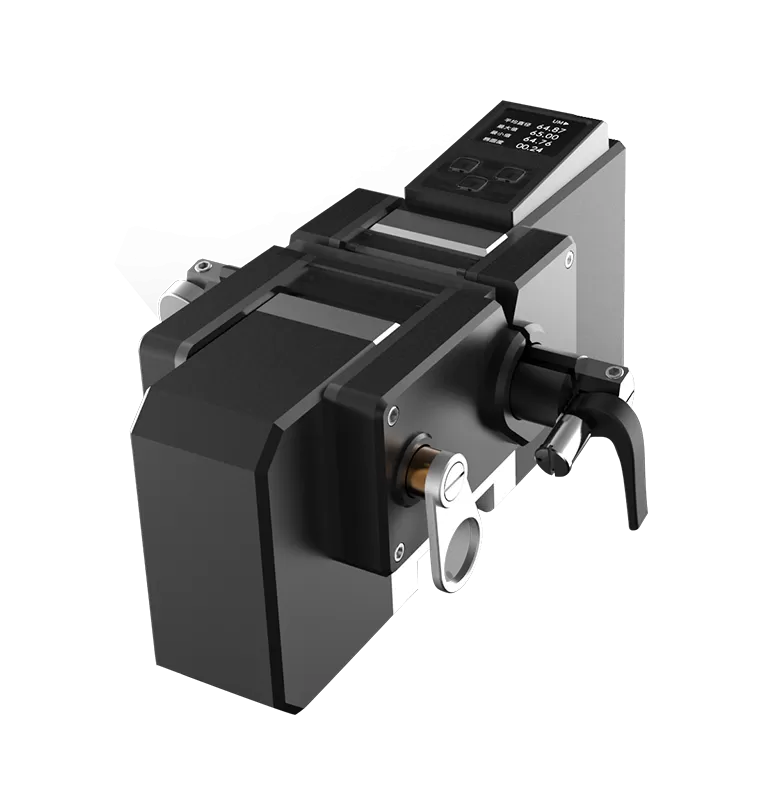
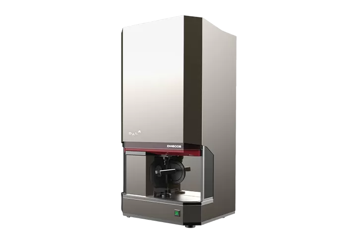
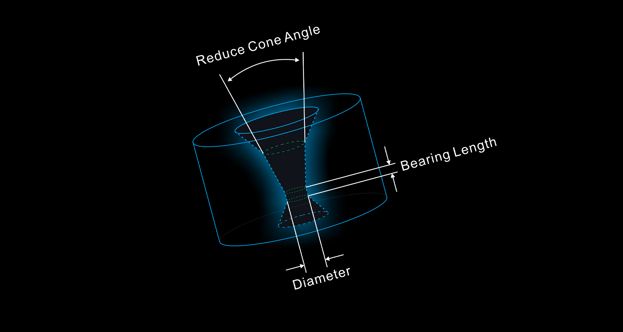
The 3D Die Profile Gauge (DM Series) adopts 3D optical imaging technology. It reconstructs the 3D profile of the inner hole via optical scanning. With one click, it can measure parameters including inner hole diameter, ovality, sizing zone length and compression zone angle in a single run. It is an essential tool for modern cable and die manufacturers to boost production capacity and guarantee product quality.
Measurement Range
0.015~45mm
Measurement Data
Diameter, Ovality, Sizing Length, Compression Angle
Measurement Principle
Telecentric Optical 3D Scanning Measurement Technology
Application Industries
Metal Wire Drawing, Wire & Cable

Product Introduction

The 3D Die Profile Gauge (DM Series) adopts the principle combining multi-axis precision optical scanning and high-resolution image acquisition. The system illuminates the die inner hole with collimated light source, and performs all-round optical scanning and 3D reconstruction of the die inner hole via a high-precision multi-axis measuring structure. The multi-axis optical system synchronously captures geometric features of the inner hole profile. Combined with high-speed image processing algorithms, it accurately calculates 3D spatial parameters such as sizing zone and compression angle. The non-contact optical measurement principle fundamentally eliminates wear and human errors caused by contact probes. Meanwhile, the system algorithm can automatically compensate for errors induced by hole deflection angle.

- Supports non-contact 3D optical scanning and 3D reconstruction of inner holes
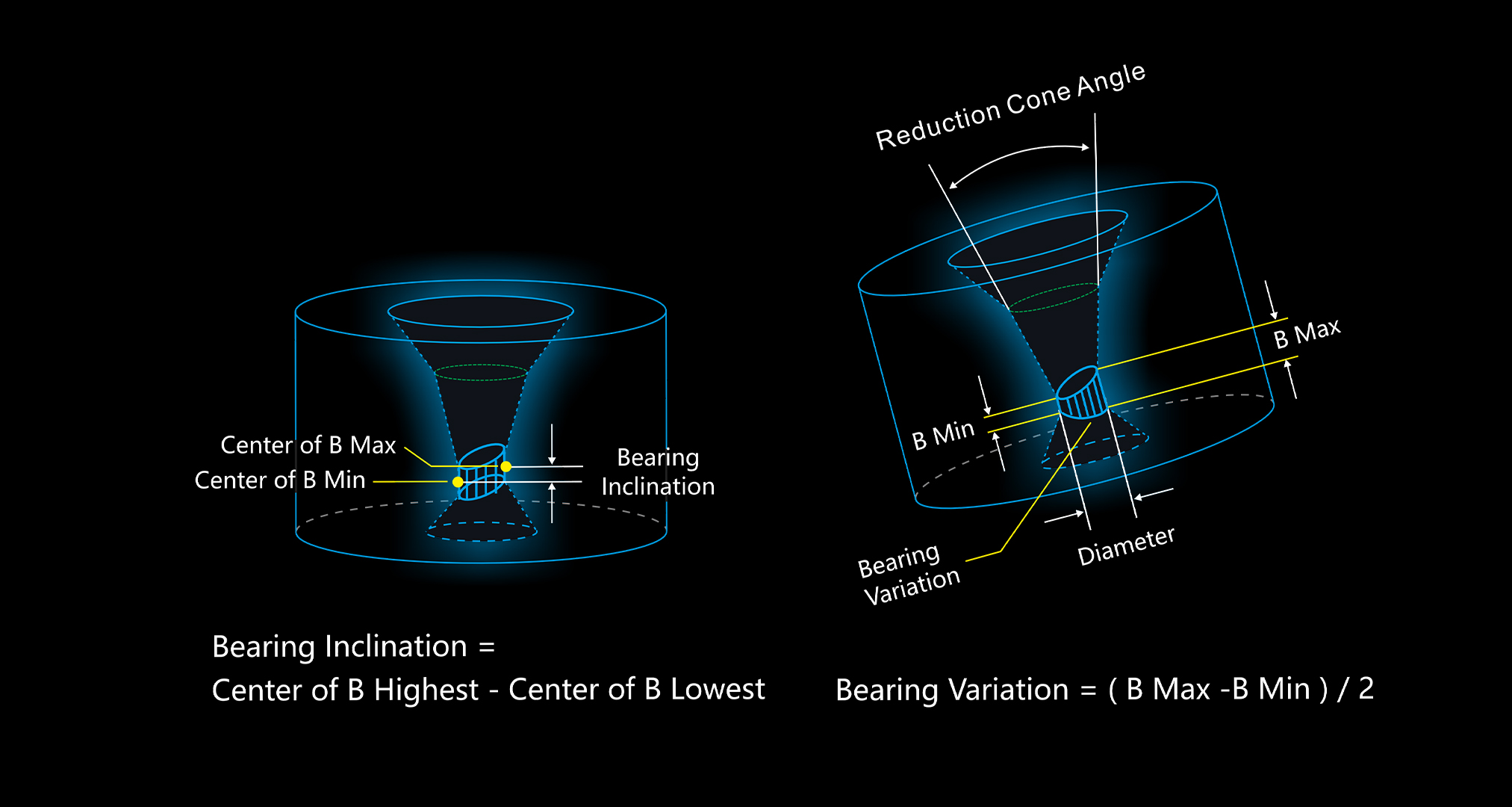
- Supports tip measurement of sizing asymmetry and eccentricity, calculated by high-precision optical system
- Built-in automatic hole deflection angle compensation. Based on 3D model spatial algorithm, it effectively reduces measurement errors caused by tilted die placement
- One-click rapid measurement with auto-focus and automatic lens switching. Single-axis measurement takes only 8 seconds, and four-axis asymmetry measurement takes approximately 24 seconds
- Visualized measurement status: observe inner hole surface conditions (such as damage and dust) in real time through the image window; out-of-tolerance alerts are prominently displayed in the data panel
- Automatic storage and export of massive measurement data: up to 200,000 records can be saved automatically; professional measurement reports are available for printing
- Supports light source calibration, system calibration and self-service software upgrade to guarantee long-term stable high-precision measurement of the equipment
- Equipped with USB3.0 data interface, compatible with mainstream operating systems
Key Features

3D Measurement, Simple and Fast

3D Measurement, Simple and Fast

The software system is easy to operate. Place the die and click once. Single-axis measurement takes approximately 8 seconds, while four-axis asymmetry measurement takes around 24 seconds for high efficiency. Operators can complete measurements without any professional background.

Four-axis Measurement

Four-axis Measurement

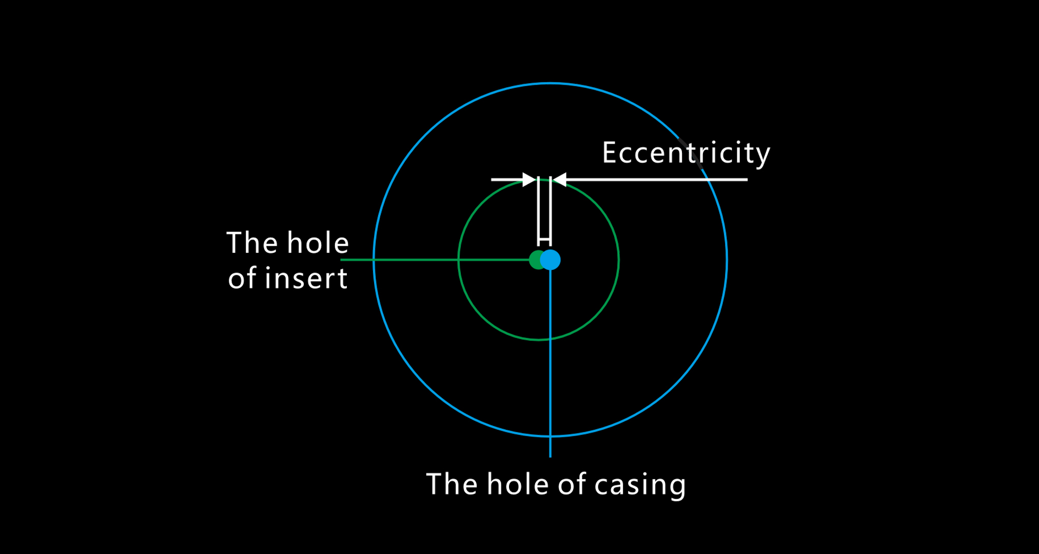
Equipped with a high-precision multi-axis measuring structure, it samples one profile cross-section every 45° to acquire profile data from 8 directions, enabling more comprehensive inspection of the die inner hole and preventing missed detection.

Eccentricity Measurement

Eccentricity Measurement

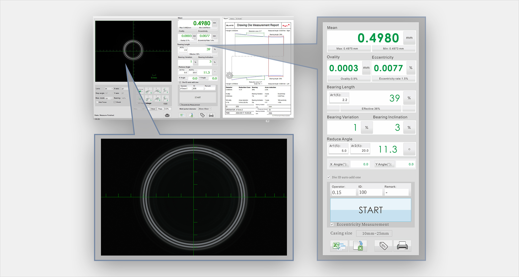
It is equipped with an eccentricity measuring stage for wire drawing dies for the first time. It can measure various die parameters and eccentricity data simultaneously, with measurement accuracy up to ±1.5μm, enabling multi-dimensional quality control of wire drawing dies.

Visualized Measurement Status

Visualized Measurement Status

The interface is clear, concise and presents comprehensive data. Users can observe the surface conditions of die inner holes (such as damage and dust) through the image window. The oversized result display area allows operators to view data from a distance.

Technical Parameters

DM600S Specifications

Lens magnification

2D measuring range

3D measuring range

Diameter/ovality accuracy1)2)3)

20X

0.015-0.200 mm

0.020-0.035 mm

±0.0004 mm

10X

0.035-0.450 mm

0.035-0.110 mm

±0.0006 mm

3X

0.110-1.600 mm

0.110-0.800 mm

±0.0009 mm

1X

0.350-5.000 mm

0.400-4.500 mm

±0.0012 mm

0.5X

0.700-10.000 mm

0.800-9.000 mm

±0.0024 mm


Lens magnification

20X

10X

(0.030~0.035 mm)

10X

(0.035~0.110 mm)

3X

1X

0.5X

Bearing length repeatability

±5%

±5%

±2%

±1%

Compression angle repeatability

±0.5°

±0.5°

±0.3°

±0.2°

Bearing asymmetry

Bearing variation repeatability

N/A

±3-6%

±2-4%

Bearing inclination repeatability

N/A

±3-6%

±2-4%

Eccentricity accuracy

±0.0015 mm

Bearing asymmetry range

0-50%

Bearing length measuring range(4)

0-70%

Compression angle range

0-32°

Max. die outer diameter

70 mm

Max. die height

32 mm

Max. die weight

0.5 kg

Measurement report print

Die profile, diameter, ovality, bearing length, compression angle, etc.

Measurement data storage

Automatic storage, up to 20,000 custom-stored records; exportable in MS Excel or TXT

Light source calibration

YES

System calibration

YES

Software upgrade

YES

Power supply

48 VDC ±5%, Max. 72 W

Data interface

USB3.0

Operating environment

Relative humidity 15~80%, temperature +15°C~+30°C, noise < 70 dB

Storage environment

Relative humidity 8~80%, temperature 0°C~+50°C

Dimensions

444D x 444W x 906H (mm)

Note:
(1) Repeatability figures are measured under conditions free from obvious air convection and ambient vibration;
(2) Accuracy data are valid when the hole tilt angle is zero. DM600S can automatically compensate for the error caused by the hole tilt angle;
(3) Accuracy data are valid when the bearing length is less than 70%;
(4) Bearing length (%) = (bearing zone depth (mm) / bearing zone diameter (mm)) × 100%.


DM500S Specifications

Lens magnification

2D measuring range

3D measuring range

Diameter/ovality accuracy1)2)3)

20X

0.015-0.200 mm

0.020-0.035 mm

±0.0004 mm

10X

0.035-0.450 mm

0.035-0.110 mm

±0.0006 mm

3X

0.110-1.600 mm

0.110-0.800 mm

±0.0009 mm

1X

0.350-5.000 mm

0.400-4.500 mm

±0.0012 mm

0.5X

0.700-10.000 mm

0.800-9.000 mm

±0.0024 mm


Lens magnification

20X

10X

(0.030~0.035 mm)

10X

(0.035~0.110 mm)

3X

1X

0.5X

Bearing length accuracy

±5%

±5%

±2%

±1%

Compression angle accuracy

±0.5°

±0.5°

±0.3°

±0.2°

Bearing length measuring range(4)

0-70%

Compression angle range

0-32°

Max. die outer diameter

70 mm

Max. die height

32 mm

Max. die weight

0.5 kg

Measurement report print

Die profile, diameter, ovality, bearing length, compression angle, etc.

Measurement data storage

Automatically stored in ACCESS database, up to 20,000 custom-stored records; exportable in MS Excel or TXT

Light source calibration

YES

System calibration

YES

Software upgrade

YES

Power supply

48 VDC ±5%, Max. 72 W

Data interface

USB3.0

Operating system

Windows 10 / Windows 7

Operating environment

Relative humidity 15~80%, temperature +15°C~+30°C, noise < 70 dB

Storage environment

Relative humidity 8~80%, temperature 0°C~+50°C

Instrument weight

80 kg

Dimensions

420D x 410W x 920H (mm)

Note:
(1) The repeatability is typically 3-5 times better than the accuracy;
(2) Accuracy data are valid when the hole tilt angle is zero. DM500S can automatically compensate for the error caused by the hole tilt angle;
(3) Accuracy data are valid when the bearing length is less than 70%;
(4) Bearing length (%) = (bearing zone depth (mm) / bearing zone diameter (mm)) × 100%.


DM300S Specifications

Lens magnification

2D measuring range

3D measuring range

Diameter/ovality accuracy1)2)3)

20X

0.015-0.200 mm

0.020-0.035 mm

±0.0004 mm

10X

0.035-0.450 mm

0.035-0.110 mm

±0.0006 mm

3X

0.110-1.600 mm

0.110-0.800 mm

±0.0009 mm

1X

0.350-5.000 mm

0.400-4.500 mm

±0.0012 mm

0.5X

0.700-10.000 mm

0.800-9.000 mm

±0.0024 mm


Lens magnification

20X

10X

3X

1X

0.5X

Bearing length accuracy

±8%

±5%

Compression angle accuracy

±2°

±1°

Bearing length measuring range(4)

0-70%

Compression angle range

0-32°

Max. die outer diameter

70 mm

Max. die height

32 mm

Max. die weight

0.5 kg

Measurement report print

Die profile, diameter, ovality, bearing length, compression angle, etc.

Measurement data storage

Automatic storage, up to 20,000 custom-stored records; exportable in MS Excel or TXT

Light source calibration

YES

System calibration

YES

Software upgrade

YES

Power supply

48 VDC ±5%, Max. 72 W

Data interface

USB3.0 (compatible with USB2.0)

Operating system

Windows 10 / Windows 7

Operating environment

Relative humidity 15~80%, temperature +15°C~+30°C, noise < 70 dB

Storage environment

Relative humidity 8~80%, temperature 0°C~+50°C

Instrument weight

60 kg

Dimensions

420D x 340W x 920H (mm)

Note:
(1) The repeatability is typically 3-5 times better than the accuracy;
(2) Accuracy data are valid when the hole tilt angle is zero. DM500S can automatically compensate for the error caused by the hole tilt angle;
(3) Accuracy data are valid when the bearing length is less than 70%;
(4) Bearing length (%) = (bearing zone depth (mm) / bearing zone diameter (mm)) × 100%.


DM300 Specifications

Lens magnification

2D measuring range

3D measuring range

Diameter/ovality accuracy1)2)3)

20X

0.015-0.200 mm

0.020-0.035 mm

±0.0004 mm

10X

0.035-0.450 mm

0.035-0.130 mm

±0.0006 mm

3X

0.110-1.500 mm

0.110-1.000 mm

±0.0009 mm

1X

0.350-4.500 mm

0.400-4.000 mm

±0.0012 mm

0.5X

0.700-9.000 mm

0.800-8.500 mm

±0.0024 mm

0.25X

1.000-20.00 mm

2.000-20.00 mm

±0.0050 mm

0.1X

4.000-45.00 mm

4.000-45.00 mm

±0.0100 mm


Lens magnification

20X

10X

3X

1X

0.5X

0.25X(5)

0.1X(5)

Bearing length accuracy

±8%

±5%

±4%

Compression angle accuracy

±2°

±1°

±0.5°

Bearing length measuring range(4)

0-70%

0-100%

Compression angle range

0-32°

0-32°

Max. die outer diameter

70 mm

160 mm

Max. die height

32 mm

75 mm

Max. die weight

0.5 kg

10 kg

Measurement report print

Die profile, diameter, ovality, bearing length, compression angle, etc.

Measurement data storage

Automatic storage, up to 20,000 custom-stored records; exportable in MS Excel or TXT

Light source calibration

YES

System calibration

YES

Software upgrade

YES

Power supply

48 VDC ±5%, Max. 72 W

Data interface

USB3.0 (compatible with USB2.0)

Operating system

Windows 10 / Windows 7

Operating environment

Relative humidity 15~80%, temperature +15°C~+30°C, noise < 70 dB

Storage environment

Relative humidity 8~80%, temperature 0°C~+50°C

Instrument weight

60 kg

Dimensions

420D x 340W x 920H (mm)

Note:
(1) The repeatability is typically 3-5 times better than the accuracy;
(2) Accuracy data are valid when the hole tilt angle is zero. DM500S can automatically compensate for the error caused by the hole tilt angle;
(3) Accuracy data are valid when the bearing length is less than 70%;
(4) Bearing length (%) = (bearing zone depth (mm) / bearing zone diameter (mm)) × 100%;
(5) 0.25X and 0.1X apply to DM300 only.


Downloads

Technical documents such as product manuals, datasheets and outline drawings

PDF
3D Die Profile Gauge(DM Series)BrochurePDF
⬇ Download

Frequently Asked Questions

Answers to frequently asked questions about 3D Die Profile Gauge(DM Series)

Q How to Select the Lens Magnification for Different Die Bore Sizes?

Lens Magnification

2D Measurement Range (mm)

3D Measurement Range (mm)

20X

0.015-0.200

0.020-0.035

10X

0.035 - 0.450

0.035 - 0.110

3X

0.110 - 1.50

0.110 - 1.000

1X

0.350 - 5.00

0.400 - 4.000

0.5X

0.700 - 9.00

0.800 -8.500

0.25X

1.00-20.00

2.00-20.00

0.1X

4.00-45.00

4.00-45.00

Q What should I do if the die bore cannot be located?
  1. Switch to a lower-magnification lens. For example, if you are using a 10× lens, switch to .

  2. Move the die stage and look for a bright spot in the software image. Once found, move the bright spot to the center of the image, then adjust the Z-axis until the double-ring image becomes clear.

  3. Switch back to the original magnification. Move the die stage again to center the bright spot, then adjust the Z-axis until the double-ring image is clear. If the image is already clear after switching back, no further Z-axis adjustment is needed.

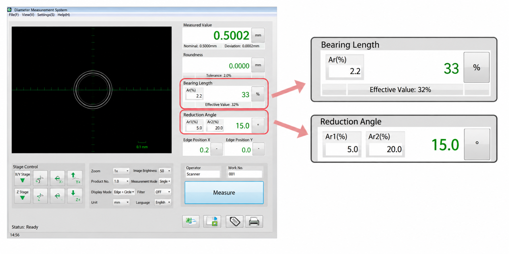
Q What do Ar(%), Ar1(%), and Ar2(%) mean in the measurement software?

Ar(%) is an input parameter used to calculate the bearing length.
Ar1(%) and Ar2(%) are input parameters used to calculate the reduction angle. Their positions in the measurement interface are shown below:

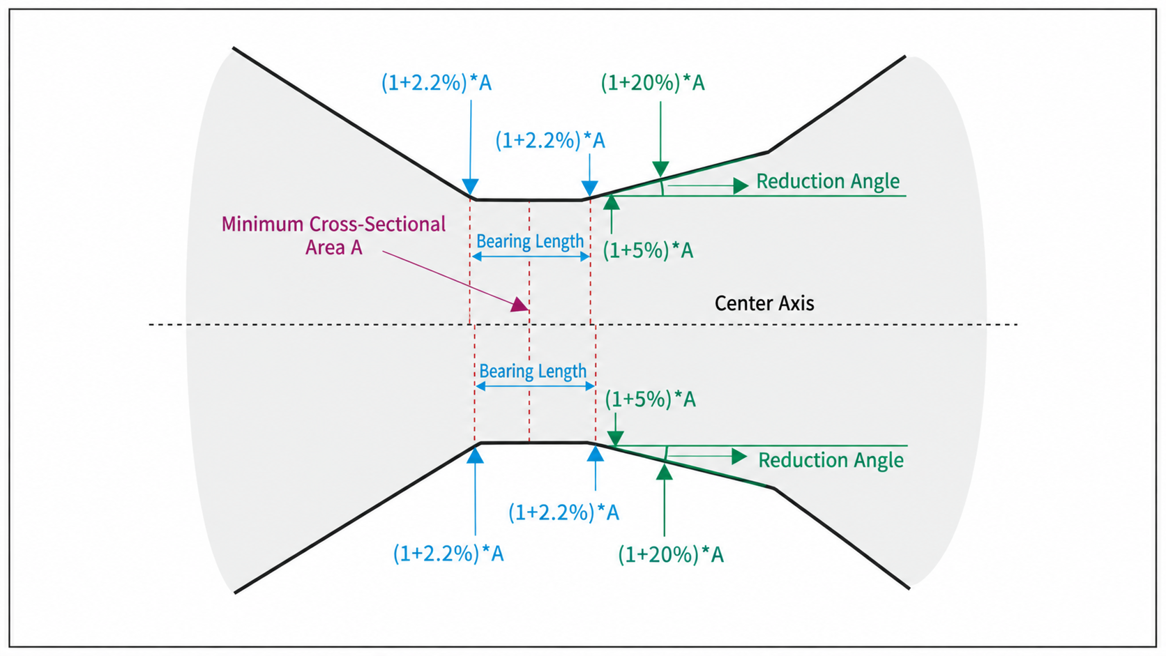
In the example above, Ar(%) = 2.2. This means the bearing length is calculated based on the position where the die bore cross-sectional area reaches (1 + 2.2%) × A, where A is the minimum cross-sectional area of the die bore.

Starting from the minimum area A (purple dashed line below), the area increases by 2.2%, creating two positions as indicated by the blue arrows. The calculated bearing length in this example is 33%.

Ar1(%) = 5.0 and Ar2(%) = 20.0. The reduction angle is calculated using the positions where the die bore cross-sectional area reaches (1 + 5.0%) × A and (1 + 20.0%) × A.

Starting from the minimum area A (purple dashed line below), the area increases by 5% and 20%, creating two positions shown by the green arrows. The calculated reduction angle in this example is 15°.

Note: The die bore cross-sectional area is calculated from the radius along the die center axis, so two bearing length values and two reduction angle values can be obtained.

Q What does the effective bearing length mean?

The effective bearing length is calculated using the following formula:

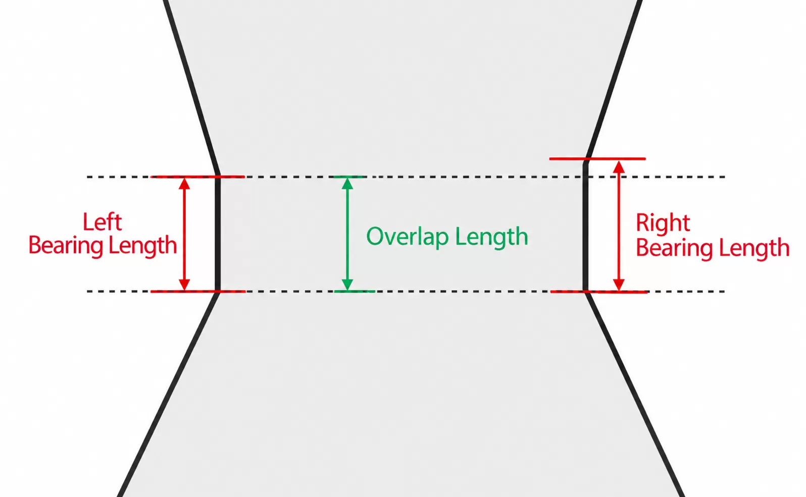
Effective Bearing Length = (Overlap of the Left and Right Bearing Zones + (Left Bearing Length + Right Bearing Length) / 2) / 2

This value is designed to represent the actual effective bearing length of the wire drawing die as accurately as possible.

Fast Delivery & Comprehensive Support

Provides end-to-end support from product selection to production line operation through on-site guidance and after-sales technical support.